Door Control Hardware
Parts
No |
Part Name |
Usage |
|---|---|---|
1 |
Raspberry 3 or 4 with power supply |
door controller |
2 |
M5Stack Mini 3A Relay Unit U023 |
door open relay |
3 |
M5Stack Mini 3A Relay Unit U023 |
door close relay |
4 |
M5Stack Hall Sensor U084 |
magnetic sensor for door closed |
5 |
M5Stack 1 to 3 HUB Unit U006 |
sensor cable extension |
6 |
M5Stack Unbuckled Grove Cable 50cm A034-C |
sensor cable extension |
7 |
Adafruit Jumperset 40 wires male/female, 15cm |
Raspi GPIO connection |
8 |
orange LED 11 mA + resistor 82 Ohms |
automatic is working (= time synced) |
9 |
green LED 11 mA + resistor 82 Ohms |
MQTT connection to broker working |
Connections
Raspberry GPIO connection:

This I/O configuration can be found on the Python/Raspberry side as config.json:
{
    "io": {
        "out_ready_led": 4,
        "out_network_status_led": 17,
        "out_open_command": 5,
        "out_close_command": 6,
        "in_door_closed": {"pin": 25, "active_state": true},
        "command_out_pulse_time_s": 2
    }
}
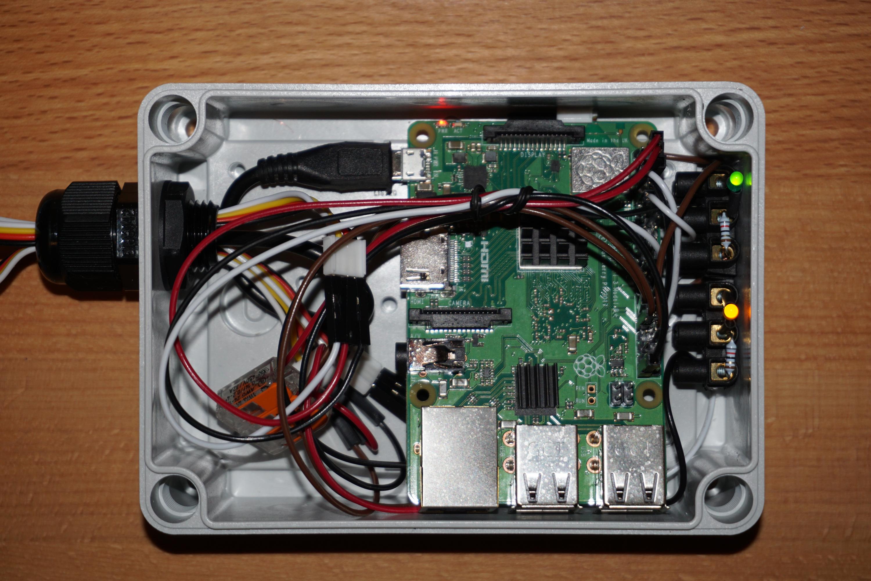
Outdoor Case
The Raspberry is enclosed in a case which is waterproof so there will not be any condensed water. It’s good enougth to control the relays.
Electrical Considerations
Some notes about the electrical possibilities and limitations of the Raspberry 3+4:
the GPIO devices must not consume more than 50 mA altogether
one single GPIO output must not consume more than 16 mA
Some outputs have a pullup and others have a pulldown behavior. If we choose the wrong behavior the startup or a reboot of the system lets the output relays switching unexpectedly. A pullup output sets the output to high until the application has been started which could be a big problem. For this project this means that the door will open or close on each startup which is an unwanted operation of the door.
So the relay outputs have to be connected to GPIO 5 and 6 which have a pulldown resistor. A reboot of the system will not lead to an unwanted switch of the relays.
GPIO power considerations this project:
Estimated limiting resistor for testing: (3.3V (measured output) - 1.7V (typical LED voltage))/20mA = 80Ohms
Voltage measurement of the used LED (limiting resistor 82Ohms): I=11mA (measured), R=82Ohm => U=R*I=82Ohm*0.011A=0.9V (limiting Resistor)
so a limiting resistor of 82 Ohms fits here for both LEDs used.
Relay coils: nominal power=0.2W, resistance=125Ohms => I=U/R=3.3V/125Ohms=26.4mA
Note
The coil current consumption is too high (26.4mA instead of 16mA) but it’s only for 2 seconds so this should damage nothing.